Finally, more diode tests

March 13, 2022

Now after finishing a few long-time projects, in particular my new digital controller system, I came to checking out a few more diodes for single longitudinal mode operation – it’s indeed been a long time since the last ones! The results are listed from here. Nothing too unexpected, except that there was a surprise: one of two samples of the Ushio HL63643DG produces more than 120mW in single mode operation! However this works only in a very tight temperature-current zone, depicted in blue at the location 148mA/21C in the left plot below:


See here for more details. This looks very promising for an ECDL setup, which I am going to look into.
Moreover I spend some time on spectrally analysing the Pico projector “White Light Engine”, which has been successfully put to work by holographers a few years back. In short, the PL530 works extremely well, the red diode borderline ok at about 20mW (for the surviving sample I got), while the blue diode seems pretty hopeless beyond a few mW.

Update: going back to ECDL’s, I checked the Ushio HL63643DG in an ECDL setup. Fantastic! About 120mW and yet not any sign of instability! At least for the diode I tested. As it looks, this may be the price-performance leader of red diodes! For details see here.

Also, the write-up of low-brow ECDL design has been updated and improved.

Digital precision laser diode controller

August 15, 2021

Finally after so many years I managed to (more or less) complete my primary long-term project, namely a super stable, low noise, fully digital universal laser diode controller system; comprising of a powerful TEC driver, a diode driver, peripheral components for automated precision measurements, with full remote control. My previous system was outdated and the specs marginal, now the specs are excellent. There are of course a zillion of little quirks still to be ironed out, mostly in software. As always, the “last 5%” take like 50% of the time of the whole project…

Now I look forward to use it for automatically determining optimal laser diode operation points, investigating ECDL lasers, etc. Maybe even doing some holography work again…..

See here for a detailed description.

Drivers, again

November 2, 2020

Here is a little update. Progress was pretty slow due to job and Corona and other things, but at least I have finished developing a new highly stable driver board which is optimized for higher power laser diodes (500mA). It is especially suited to the OPSL PL530 modules, as it contains also a PPLN heater circuitry, all with the same footprint as before.

Here is a pic showing a breadboard setup, plus the first version to the upper left (still using the L5973D as PWM chip for the TEC), then a second version to the lower left (using the more powerful LM2673 plus external sense resistors for the LD driver):

For details see here.

PL530 and more

January 11, 2020

While I was largely inactive for quite a while, the world continued to change and thanks to George S. and Dave B. I got updated about a stunning development: the tiny Osram PL530 530nm OPSL modules (intended for laser projectors) run very easily single longitudinal mode even up to about 100mW!
See here for a discussion relevant for holography.

This means that the $10 device of the size of a coin, is as suitable for holography as my old Lexel 88 argon ion laser and the Coherent Compass 315M laser! The construction of the power supplies of which had been major projects by themselves…. The only downside seems is a slightly lower beam quality, at least before correction.

Of course this called for a closer investigation, which means first of all a scan of spectral line width over the operation parameters, which are laser diode current and PPLN heater resistance/current. Some years ago I used a computerized setup for scans of laser diodes and ECDL’s, but surely enough the USB driver didn’t work any more on new computers, so I first had to rebuild the digital control hardware, plus write new software.

This is finished now and all works better than ever: also at the microcontroller front there was dramatic progress, and now I use dirt cheap ESP8266/ESP32 eval boards that also offer easy Wifi connection and powerful LCD drivers, apart from more speed and memory.

Then I put a PL530 module into an existing laser setup where I could make good use of one of my 500mA laser diode drivers/TEC controller boards. The TEC stabilizes the case of the PL530 which is clamped against it. What was needed in addition was a stable driver for the heater current which is the most critical quantity to control. It keeps the resistance of the PPLN heater element (which acts as a PTC thermistor) constant, and uses a bridge setup similar to the one desribed here (with some modifications to allow for digital control).

PL530 test setup

Now all was ready to take measurements (click above for a movie), and here are first results:

PL530 scan

To the left, there is a scan of the line width over laser diode current and the heater current, much like I was doing for laser diodes and ECDL in the past. Blue denotes regions with singe longitudinal mode operation, and red multimode.

In the middle the noise in the laser output is shown. The hope that noise would reliably indicate multimode operation, which is typically the case for many laser diodes, was not fulfilled. So there seems no easy way to reliably find a single mode operation spot without extra equipment.

Nevertheless, as shown at the right which displays the output power, the maximal power region coincides, fortunately, with single mode region! So in this case tuning to maximal power (about 105mW) also leads to single mode operation. There is no a priori reason for this, and it remains to be seen to what extent this simple criterion suffices also more generally.

I plan to write over time more details about this, including some more measurements, on my website here (under construction).

Update

May 14, 2017

Now I am done for the time being with analyzing the ultra low noise Zener diode 2DW23x, including building low noise measurement amplifiers. Some summaries can be found here and here. What remains are long-term burn-in and stability tests which run 24/7 for about half a year.

The motivation was to develop a digitally controlled ultra-low noise laser diode drivers for holography applications. This is a long-term project too. In the meanwhile, some first development prototypes were made, and eben without too much effort they sport already very low noise. The only noteworthy thing is that there was at first a considerable feed-through via the DAC from the I2C digital bus. This was completely eliminated by using an opto-coupler – not just for galvanically isolating the bus but rather for interrupting any communication to the DAC except for a brief moment when the output current needs to be changed.

Here a picture of the current test setup, soon it is time to draft a first PCB version:
LD proto

In the middle there is an Arduino Nano, plus DAC/ADCs for digita/analog interfacing via I2C bus. To the left a low power (1.5A) PWM TEC controller for testing. On the right I used a left-over PCB from my old analog TEC/laser diode driver, for the actual analog current output driver including precision, bulk metal foil current sense resistors.

Arduino-shield high precision TEC controller for laser diode holography

December 10, 2016

Finally, after more than 1/2 year of work this project is completed; well, almost, I still need to tweak software, but I won’t have time for the rest of the year. Here is a quite exhaustive writeup, so nothing needs to be added for now in this blog.

The plan is to develop next another Arduino shield as a companion, very stable laser diode driver. This will be hard since noise and stability requirements will be harder, and not easy to reach given the noisy digital environment. As preparation I have set up an extremely sensitive low noise amplifier for measurements (see previous post).

Moreover, a miniature combo board of TEC and laser diode controller is planned, but only after having gained more experience with the present controllers.

I may sell some of the controllers at a later time once the complete package incl diode driver is done and turnkey useable.

pcb2

Some intermezzo in repairs and metrology

November 23, 2016

While I was slowly progressing with my Arduino based precision peltier controller (update soon), I stumbled over other things that took some time to sort out.

First, my valuable ultra precision 8-1/2 digit Datron 1281 DMM stopped working. I spent some time checking voltages, ripples, ROM images, but this seemed to be a more subtle problem and threatended to tie me up indefinitely. So I sold in on ebay, and got in return as much such as to afford a brand new Rigol3068. This has only 6-1/2 digits but this is enough for my various applications (temperature and laser current control).

I am very happy with the Rigol3068, it sports also an Ethernet connection which helps me to go beyond GPIB control which gives problems all the time. An advantage is also that it has 240000 counts, which means that I can measure 10K Thermistors (at around 13KOhms or so) with full 6 1/2 resolution in the 20K range, rather than having to use a more typical 100K range which cuts down by a factor of 10 in resolution. So I can safely resolve temperature differences of 1/10000 degrees.

When tinkering around I remembered I had also a faulty Solartron7081 8-1/2 digit voltmeter around and looked again into it. It had intermittent thermal problems and I had repaired a few of them by replacing ILQ74 optocouplers a few years ago. Still, some mysterious 80uV jumps remained without explication, plus an elevated noise level of about an order of magnitude larger than expected. Such things are notoriously difficult to get a handle on.

While at it, I stumbled over the eevblog which adressed these questions in this thread (me calling myself bertik for silly reasons). So I managed to relate these jumps to a faulty auto zero mechanism, which I circumvent by disabling it.

While investigating there was a serious setback: when checking the current setting for the reference Zener, I inadvertently shorted the test pin 301 with the – input of IC 304 (refers to service manual). There was a sense of smoke, which was surprising, since this test pin is supposedly at ground. I checked and alas, there was 17V AC voltage at it! With source impedance of like 2 Ohm… how could this possibly be? Was it the effect of the short? How can 17V AC go straight into the reference voltage section?

After disassembly it turned out that the test pin was wrongly placed by the manufacturer, namely on a via. And indeed there is 17V AC voltage there, fed across half of the board to a few mm near the reference section (!). It enters IC303 which is close by. So that explained it. As a consequence, IC 301 and IC 303 where blown and possibly more.

I decided to by-pass this problem by substituting an (aged!)
+10V/-10V precision reference
VRE102CA of which I had salvaged a few from trash. It can be made fit perfectly into the reference section of the 7081, by attaching the outputs to the reference terminals TP 302/TP 303 and opening the base and collector connections of TR 301 and TR 302. This works as good as before, the reference has like 1ppm/C temperature stability and like 3uV pp noise 0.1-10Hz.

For the time being I’ll leave the reference section like that, since the excessive noise problem is the next pressing one. I will report on any progress in the future.

Solartronrepair

How do I know the noise level? This has to do with another thread on eevblog, namely this thread. There a DIY low frequency noise meter was described, and this is what I wanted anyway, for various reasons. First, for checking out various voltage references that I am going to use for laser drivers. Then, primarily, to measure low intensity noise of the laser driver outputs. I like to get below like 1uA pp noise at about 200mA. So this calls for proper measurement hardware.

Given the valuable tips of very competent people in ths thread, I quickly built my own version. It works fine with a base noise level of 200nV pp at 0.1-10 Hz. I use only half of the dual opamp since I shot the other half ;-(, otherwise it would be in the order of 140nV pp. With this in hand, I characterized differend voltage sources, which is important also to judge the disease of the Solartron7081. Here a few results — more to follow:

VRE102CA (10V): 2.7 – 5uVpp, depending on specimen
VRE102CA (10V), two parallel: 1.9uVpp, 0.33uVrms
MAX6250 (5V): 1.6uVpp 0.32uVrms
Data Precision 8200 Calibrator (10V): 12 uVpp, 1.9 uVrms

Base noise, 200nV pp:

BaseNoise

(100mV corresponds to 1uV).

Dual VRE102CA noise, 1.9uV pp:

VRE102CAdual

The tips in the DIY low frequency noise meter thread were extremely valuable, in particular the issue of leakage current of the input capacitor. I never thought that this could be handled with hobbyist means. But indeed checking out a few caps I had around, there were some with <1 nA leakage current, so this was fine! Still this is a slightly tricky business.

Here are some extra comments:

1) Shielding: an aluminum case with slots on the sides didn’t work at all due to overwhelming 50Hz noise. One really needs a kind of watertight shielding, I used a classic Teko case intended for RF applications. Actually two nested ones, the outer one holds battery and supply voltage splitter. I also use switcheable bandwidth control because sometimes I may be interested to go beyond 10Hz.

Low Noise AC Amp

2) Ground loops. When measuring references in existing other setups, one is more or less guaranteed to get ground loops, at least if the scope input is grounded. This shows itself in an elevated noise which does not necessarily looks suspicious. I noticed it when connecting the input to a function generator to track the frequency response (via a 1M/10 Ohm divider).

The solution was to put between amp and scope an extra isolation amp. I use an AD210AN which I had at hand, and I also added an extra gain factor of 10, so the total gain is 10^5. This means 1uV AC input will come to 100mV output.

isolation amp

Now the story continues to go on, in a related direction, since in this thread it was discussed that ultra-cheap Chinese Zener diodes may have noise levels which are lower than the best industrial references. This created a group buy frenzy which reminded me of the one of a few years back about the blue 1W laser diodes – a gold rush type excitement where people buy dozens if not hundreds. Obviously I couldn’t resist to order a dozen or so as well, for potential application to ultra low noise laser drivers.

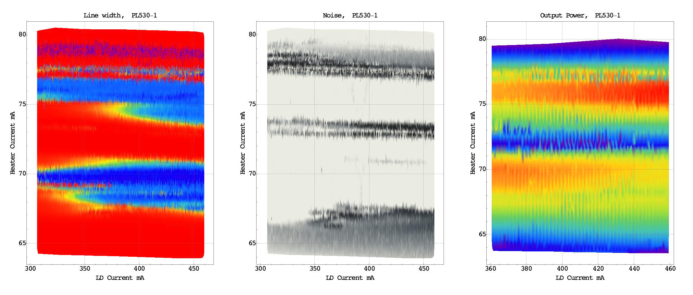
When these little gadgets arrive, I will conduct tests which are quite similar to what I was doing for laser diodes since years: automated high-precision scans over temperature and current. Let’s see what will come out, stay tuned.

Ultra stable TEC controller as Arduino Shield

May 31, 2016

I didn’t have time for my hobby for a long time, but recently I got around restarting some lingering laser related projects. One thing I felt was needed is an update of my stable laser diode and TEC drivers for holography applications. See here for background. In short, one needs to avoid mode hops by having an exceedingly tight diode current and temperature control. We are talking about stability of the order of 1/1000 degree for extended periods of time. This is in particular critical for ECDL lasers.

This new project was partly motivated by requiring bi-directional drive (so cooling AND heating), so one does not need to run the laser below room temperature. This necessitates a H-bridge PWM drive mode, and this is already close to full digital control. The other motivation was the design of solarfire and dnar and others described in this forum. However that design is not stable enough and also I am not familiar with the microprocessor. So I decided to come up with a stability-improved design, based on the Arduino. It is dirt cheap (whole ready-to-use boards for less than 3 Euro incl shipping..) and there exists lots of useful software for it.

However in order to meet design goals, one has to make some efforts in the hardware and software design. Hardware means precision opamps, voltage references, and <=5ppm/C stable resistors. Fortunately I have a large stockpile of those.
Software means to bring inputs and PWM outputs to like 16bit resolution, which is far more than the usual 10bit ADC input and 8bit PWM output resolutions. Strictly speaking 16bit PWM output is easily possible but then the PWM frequency is a few kHz and this requires an enormous amount of filtering increasing size and also noise pollution. In fact I managed to cook up a software solution for the PWM driver that gives 16bit resolution while still running at 62.5khz! And input wise with suitable oversampling and “dithering” the resolution can increased to 16bit as well.
This avoids expensive 16bit ADC’s.

So all in all, here are the main features of the design that are working as of now:

-full H-bridge for bi-directional TEC drive
-up to +/-3A current
-temperature stability < 1/1000 degree for hours
-noise level about 2/10.000 C
-control via USB serial terminal, optionally LabVIEW
-LCD display
-automatic PID control loop configuration per pushbutton
-saving basic operating data in EEPROM
-ready interface for companion diode driver

So far only a development prototype exists, but I am about finishing
PCBs which could be used as add-on shields for the Arduino Uno.

My plan later is to make an update for the LD driver too, giving another Arduino shield which can be stacked on top. This setup is supposed to be suitable for desktop laser diode controllers.

Finally a miniature version is planned with less power (1.5A), where both TEC and laser drivers are on one board and a stacked-on Arduino Nano is used for control. This setup is supposed to go into compact laser heads.

Here a picture of the LabVIEW interface showing stability of a few 1/10.000 degrees.

Website being moved

April 27, 2015

I was changing provider and so my web site of many years will have a new address:

http://hololaser.kwaoo.me

Some links might not yet work but I will slowly correct it.

Some more diode tests

January 5, 2014

Finally I completed over the holidays a bunch of further diode tests with regard to single mode operation, mostly in ECDL setups. I had collected them over the years but didn’t have enough time to actually do it. Hopefully I’ll be more active again in the future.

In brief, the results are as follows:

    • Mitsubishi ML520G71 300mW/635nm, Opnext HL6388MG 250mW/640nm, Mitsubishi LPC-836 300mW/655nm diodes:
      unsuitable
    • Opnext HL63603TG 120mW/638nm/3.8mm laser diode:
      very good ECDL to 60-70mW
    • Mitsubishi ML520G54 110mW/638nm laser diode:
      very good ECDL to 60-70mW
    • Osram PL520 50mW/520nm laser diode:
      good ECDL to 40mW

Further details can be found here. As a spoiler, here a brief movie (2.7MB) of a test of the green Osram, which shows stable single mode operation at around 40mW:
.

Happy New Year!